


Service promises:
Service before and in sales: In these periods, we will answer any technical inquiry or question and help client to select type of flow-meters based on clients' technical requirements and real world circumstances.
After service:
1. Location service:
Our company will dispatch technical engineer. The engineer would take charge of directing installation, testing, and training. Training includes how to installation, testing, setting, operation and maintenance. One year warranty after sold includes free repair and exchange. Lifetime maintenance after one year just pays cost of damaged components.
2. Other promises:
1.After sold, the product would be delivery free to the local station of client by train or truck.
2.Warranty is one year. In warranty period, we guaranty that give proposals for solve problems in two hours; arrive to the location for service or express delivery parts after conferring with client in 48 hours. Except of improper operation or knowing damage.
3.If the product software updates, the client's product software updated free.
4.After installation, we will survey and collect feedback information of client often by telephone, letter and interview. And to persist client's satisfaction, we should meet client's requirements, deal with client's complain properly.
Installation and Operation:
Every meter consists of two parts: the sensor (primary meter) and the transmitter (secondary meter).
The sensor (primary meter) is machinery part of mass flow meter. There are a vibrator, two displacement sensors and a temperature sensor in it.
The transmitter (secondary meter) is display part of the meter, also is electrical part. There are power supply, analog circuits, digital circuits, displayer, and output circuits and so on in it. Its foundational functions are receiving and regulating the electrical signal from sensors, directly getting mass flow, temperature and density after regulating, and calculating volume flow and other need parameters from known parameters. It can display, output, store and long distance transmit, and you can modify the parameters of flow meter. There is a diode safety barrier in transmitters; the function of the diode safety barrier is safeguard to isolating explosion.
As the composite explosion-proof flow meter, the sensor (primary meter) is essential safety; the transmitter (secondary meter) is explosion isolated. The sensor and the transmitter may all operate under hazardous area.
As the essential safety flow meter, the sensor (primary meter) can operate under hazardous area, the transmitter (secondary meter) must only operate under prescriptive safety area (see section 3.2), forbidden to operate under hazardous area.
1. Installation, Adjustment and Operation
1.1 Installation of meters
The mass flow meter type of KLB-CMFI mostly is divided to two parts: a sensor (primary meter) and a transmitter (secondary meter), a shield cable connects two parts. The transmitter (secondary meter) of the essential safety flow meter must mount in safety area according to prescriptive conditions. A sensor and a transmitter of the essential safety flow meter installation show in Figure 1.
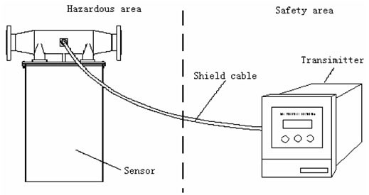
Figure 1. Sketch of Essential Safety Flow Meter Installation
The transmitter (secondary meter) of the essential safety flow meter normally fixes at a cabinet. Drill a square hatch 152mm X 152mm on panel of cabinet; install the transmitter with attached securing plates, nuts and screws referring to Figure 2.
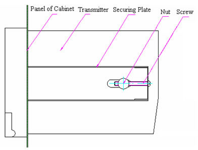
Figure 2 Essential Safety Transmitter Installations
The transmitter (secondary meter) of composite type mounts on the sensor (primary meter) with attached screws. A shield cable connects two parts.
Installation of the sensor shows in Figure 3, illuminate hereinafter now:
(1)The mass flow meter type of KLB CMFI normally installs in level line, main body perpendicularity downwards. PLS pay attention to the direction label on flow meter, should be same as the direction of fluid in line. If can not confirm direction, PLS see Figure 3, while the cable socket on back of the mass flow meter, flow direction is from left to right;
(2) Securing supports should be built in upper and lower reaches of a line beside the flow meter;
(3)Ensure concentric with two flange of flow meter and line while installation. When screwing, screws should be forced uniformity symmetrically, do not impose contraposition, forbidden wring or bend the primary meter;
(4)Definite back pressure should keep in lower reaches of a line behind flow meter. Do not let line direct open, prevent incorrectly measure while half tube of liquid;
(5)The sensor (primary meter) must leave up ground, and do not touch anything, except of type of DN6 and DN10;
(6) The tube of upper reaches of line must equal or large than the meter’s inner diameter, forbidden to less than;
(7) The body of sensor should be covered with heat preserved material, for measuring the liquid that easy gasifies. Or, the sensor may be damage with frost or dew;
(8) For type of DN6 and DN10, the sensor should install on ground, use soft tube to connect to the lines;
(9) The serial number of sensor and transmitter should same, if the serial number not match, the error may be bigger than normal;
(10) PLS contact us if you need any special installation.
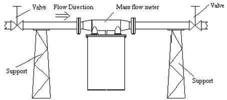
Level line:
Main body is adown.
Measuring liquid.
Exit must higher 0.8 meter than the line
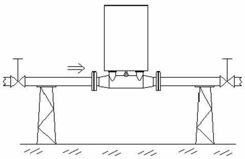
Level line:
Main body is upwards.
Measuring slurry.
Exit must be higher than the top of main body.
Upright line:
Flag install.
Measuring liquid or slurry.
The direction of fluid must be upgrade.
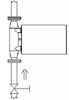
Figure 3. Sensor Installation
1.2 Conditions required of installation
To guarantee the accuracy, conditions required when installation should be met, because the mass flow meter type of KLB-CMFI is a high precision instrument:
(1) The sensor (primary meter) and the transmitter (secondary meter) do not install in strong magnetic interferential area. Or, measuring signals would be disturbed, and debase the accuracy;
(2) There is must not any other vibrator on line installed the sensor (primary meter);
(3) If install outside of door, PLS pay attention circumstance temperature not to exceed the range of meter, and should consider to build a weatherproof shield to avoid blowing and drenching, for increasing lifetime of flow meter.
(4) The transmitter (secondary meter) of essential safety should mount in safety area or appropriate control room.
(5) A shield cable with ten core lines connects the sensor (primary meter) and the transmitter (secondary meter) of essential safety.
The output cable of the transmitter (secondary meter) of composite is a shield cable with ten core lines.
Five meters long of the cable is normal option in package by our company. Customs can deal special order for longer cable, but not exceed 200 meters.
1.4 Operation of Transmitter (secondary meter)
The transmitter (secondary meter) is the electric part of mass flow meter, also is core part of data control and display.
1.4.1 Transmitter of Essential Safety
There are a display window, three key-presses, a synchronous return-key and a power switch on the front panel of an essential safety transmitter of flow meters. A power socket, a ten-pin connecting port and a twelve-pin connecting port are on the rear panel. A diode safety barrier mounts in the transmitter.
1.4.1.1 Rear Panel Description of Transmitter of Essential Safety
The rear panel of essential safety transmitters of flow meters shows in Figure 4.
A ten-pin connecting port is on first column in right of rear panel. From up to down, first and second pins connect to the vibrator in the sensor (OUT, GND); third,fourth and fifth pins connect to right and left displacement sensors separately (L1, GND, L2); sixth, seventh, eighth and ninth pins connect to the temperature sensor (+Tem1, +Tem2, -Tem1, -Tem2); tenth pin connects to shield of cable (Shield). The wire colors of cable connected to pins from one to ten are brown, red, orange, yellow, green, blue, purple, gray, white and pink.
A twelve-pin connecting port is on second column in right of rear panel. From up to down, first and second pins output 4mA~20mA current loop of channel 1 and channel 2 (Curr1, Curr2, ); third pin is ground of current loop of two channels (GND); fourth and fifth pins output 0Hz~10kHz frequency signals of channel 1 and channel 2 (F1, F2); sixth pin is ground of frequency signals of two channels (GND); seventh and eighth pins are not used (N.O.1, N.O.2); ninth and tenth pins are RS485 data communication (A, B); eleventh and twelfth pins used to clear mass of batch (CALM, GND), press the push button connected to these ends would clear volume gross of batch.
Power socket is on lower left of rear panel, power is AC 220V/50Hz.
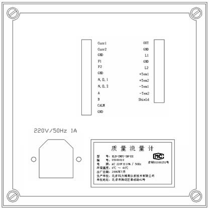
Figure 4 Rear Panel of Essential Safety Transmitters
1.4.1.2 Front Panel Description of Transmitter of Essential Safety
The front panel of transmitters of essential safety flow meter shows in Figure 5.
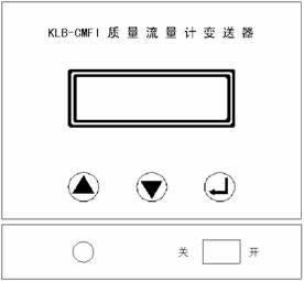
Figure 5 Front Panel of Essential Safety Transmitters
Tel :8610-88148118 8610-88148119