


The display window is on center of front panel, it displays datum and information.
Three key-presses are under the window. From left to right, they are an up-key, a down-key and a return-key. Operation of a transmitter mainly uses these key-presses. Open the cover under the key-presses, there are a synchronous return-key and a power switch.
Attention: The return-key would be action just while it is pressed with the synchronous return-key at the same time. The synchronous return-key can prevent improper operation.
1.4.2 Transmitter of Composite
There are a display window, an up-key, a down-key, a return-key and a synchronous return-key on the front panel of a composite explosion-proof transmitter of flow meters. The transmitter has two cable output: One short cable with plug connector connects to sensor (primary meter); another long ten core cable provide to user.
1.4.2.1 Transmitter of Composite wiring Description
Inner rear cover of transmitters of composite explosion-proof flow meters shows in Figure 10. A diode safety barrier installed in rear cover of transmitters of composite explosion-proof flow meters, blue connectors on the diode safety barrier connected to the vibrator, displacement sensors and temperature sensor of primary meter. There is a output connecting plate on the diode safety barrier. Marked CUUR2/F2 factory had configured CUUR2. Marked N.O.3 and N.O.4 are contactors of batch control relay 2. Marked CLEAR and GND could connect a push button for manual clear batch control mass value. N.O.3, N.O.4, CLEAR and GND had not connected to the output cable. User should not open the front cover. If need, must open rear cover to re-connect output cable by our factory technicians.
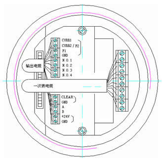
Figure 6 Inner Rear Cover of Transmitters of Composite
The transmitter has a long ten core cable output, providing to user, see Figure 6. They are:
1.current loop outputs: channel one output CURR1 (brown)
channel two output CURR2 (red)
2.frequency outputs: channel one output F1 (orange)
3.common ground of current and frequency: GND (yellow)
4.contactor of batch control relay 1: N.O.1(green)
N.O.2(blue)
5.RS485 data communication: A (purple)
B (gray)
6.power supply +24V (white)
7.common ground of power: GND (pink)

Figure 7 Composite Flow Meter Connecting
One common ground (GND) is for current loop and frequency, another (GND) is for calibration and power, should not confuse!
1.4.2.2 Front Panel of Composite Description
The front panel of transmitters of composite explosion-proof flow meter shows in Figure 8.

Figure 8 Front Panel of Composite Flow Meter
The display window is on center of front panel, it can display datum and information.
Three keys are under the window, one key on top. These keys are magnetic switch keys. Use special magnetic pens close to the key for operation. From left to right under the window, they are an up-key, a down-key and a return-key. The key on top is a synchronous return-key.
Attention: The return-key would be action just while it is operated with the synchronous return-key at the same time. The synchronous return-key can prevent improper operation.
2. Calibration
Type of KLB-CMFI mass flow meters are high precision measurement instruments. For guarantee accuracy in use, must calibrate by the metrology department periodically. Calibration operations as follows:
Direct to measure frequency output of the meter, see the manual for connecting and specifications. Mass flow upper limit should be input in configuration menu in advance, the value of limit is corresponding 10kHz frequency output. Select the channel number just configured in normal operation menu then can calibrate.
If result of calibration exceeds the error, could modify the fluid coefficient k based on the result. New fluid coefficient k1 calculating formula is as follows:
k1 = k0 * mfs / mfd
Herein: k1 — New fluid coefficient will input to secondary meter;
k0 — Old fluid coefficient memorized in secondary meter;
mfs — Mass average got by the calibration standard;
mfd — Mass average got by secondary meter display.
3.Trouble Shooting
Trouble shooting table(Table 1)
Troubles |
Reasons |
Removing |
Value of dp is not steady |
Installation was incorrectness |
Install again follow 5.1 |
dp is sometime big or small |
Setting Zero was of no effect |
Check-up connection between the transmitter and the sensor |
Display “Vibration Stops” |
Bad connection, or dirty inner tube |
Check-up connection or clean inner tube |
Display “Density Too Low” or density is sometime big or small |
There is gas in tube |
Discharge gas or equip a gas-liquid separator |
Density has error |
After installation |
Adjust density coeff. b |
Not working (display not changed after power on) |
Power off too short, or power-cord bad contact |
Power off for 10 seconds, keeping fine contact |
Display minus flow |
Setting zero at flow, or valve close not tight after select dp-0 |
Do not select dp-0, setting zero follow this manual |
No communication signal on upper computer |
Check-up connecting lines was not broken |
Exchange A, B connection |
Communication of upper compute sometime mistake |
Program of communication is good |
Change a good RS232/485 converter |
Testing parameters for normal sensor:
Driving coil (1-2 pins): resistance: <50Ω; ac voltage: 1V±0.5V
Testing coils (3-4 or 5-4 pins): resistance: <100Ω; ac voltage: 0.5V±0.3V
Temperature resistance: (7-8 pins): 100Ω±10Ω (when 0℃),coefficient≈0.38Ω/℃
Temperature resistance: (6-7 or 8-9 pins): 0Ω±2Ω
4. Attentions and maintenance
Lifetime of the meter is relative with care and maintenance. To extend lifetime of the mass flow meter, should care and maintain best as follows:
(1)Keep clean for sensors and transmitters; do not put transmitters in dusty place;
(2)Move sensors and transmitters gently, do not throw or break;
(3)Should rinse inner tubes of the sensor periodically, shorten clean period for glutinous fluid;
(4)Examine and repair regular. Periodically calibrate by the metrology department for nicety measurement customers
Tel :8610-88148118 8610-88148119